

With the check-engine light taken care of, the car at least thought it was behaving properly, however there were two big issues that were still dogging me….well three.
- The car didn’t want to run when it was cold, it would chug and stall unless I kept my foot on the gas. This was for the first few minutes until it warmed up. This was due to having absolutely no idle speed control.
- The car ran like absolute garbage during this time.
- It started stalling at traffic lights.
- I was still only getting 1.2 bar on the boost gauge
I guess that’s four. We’ll address these issues in order.
For starters it was clear that I had an issue with the idle speed control circuit, as in, it just wasn’t doing a darn thing. The base Idle Speed in this car has a mechanical setpoint. The idle speed is then adjusted by an air bypass valve controlled by a module outside the realm and knowledge of the ECU. This system increases airflow into the system ( and hence raises the idle speed) under certain conditions.
The inputs to the control module are:
- +12v Power (duh)
- Coolant Temperature
- AC Compressor active signal
- Instrument cluster speed signal
- Radiator Cooling fan active signal
- Idle mode signal
- and probably some others I’m forgetting.
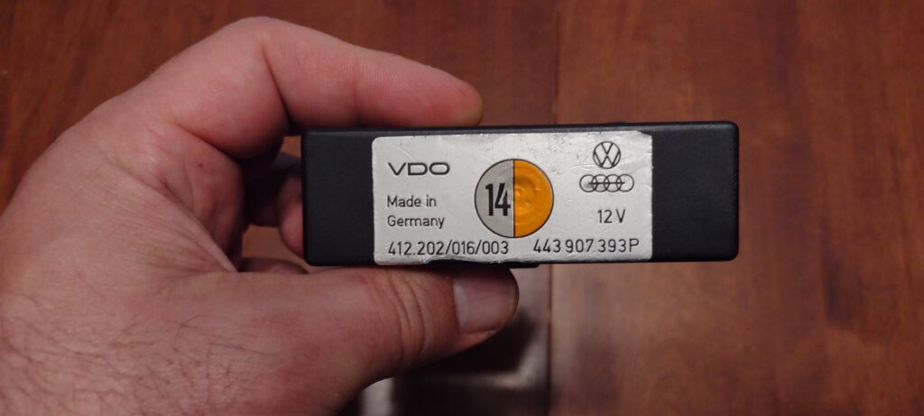
The system will adjust the idle speed a little or a lot depending on those various inputs. You’ll note it doesn’t take an RPM reference speed to try to achieve a target or anything. It assumes a known baseline and simple adds some number of volts to the air bypass valve according to some calculatio ( x number of volts = y rpms). Reading on forums, folks say the first thing to check are the resistors in the unit, as there’s one in particular that goes bad and messes up the entire works.
So, I opened it up and, yeah that looks pretty toasted. (Don’t mind the torn ribbon cable, that disintegrated on me pretty quickly, but was intact when I started.)
I took an inventory of all the capacitors inside as well, figuring I might was well replace them too.
And here you can see a nice new resistor with some pin headers to keep things simple. Also note the new red capacitor in the lower part of the board. One thing I did learn when recapping this board is that, the traces on this thing are super duper fragile, and I ended up completely nerfing a couple pads and traces along the way. So there are currently about 4 different bodge wires and solder bridges. Not my best work, and when I lifted my 3rd pad I was starting to have a serious bout of “Did I forget how to solder?”
Anyway, excited about my handy work, I plugged it, crossed my fingers…and NOTHING. It still wasn’t doing anything. I was devastated. I kept driving the car as it had been pressed into service as my Daily Driver at this point. After some number of months of chugging and sputtering through the neighborhood first thing in the morning, I found another of the exact part number: 443.907.393P on ebay about $100. I ordered it, because I was 100% convinced I screwed up the rebuild with all the lifted traces and what not.
A note on Audi Part Numbers. That little P suffix on that part number is critical. These modules were used across the Audi / VW line in anything with the Bosch CIS fuel injection system, but they were VERY application specific, because different systems had different accessories and different loads which needed different amounts of voltage supplied to the valve under different conditions — all denoted by the suffix on the part number.
Anyway, do you want to know what happened when I plugged the new one it? Yep you guessed it. Nothing. This meant I’d been chasing my tail for months on this and the problem was elsewhere. So, I went back to the drawing board and started testing all the inputs to the control module AGAIN.
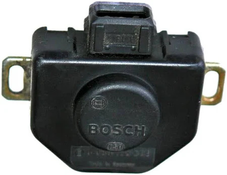
I found that the throttle position switch wasn’t actually working. This switch comes in the form of a little black box. The armature from the throttle plate goes in one side. When you’re foot is off the gas, it closes one set of contacts with tells the computer “We’re in idle mode!”, when you’re flooring it to get out onto the highway, it closes another set of contacts which says “We’re going for it Hoss!”. So basically, the computer has three operating environments. Idle, driving, and YAHOO!
Well, I found it was never sending the idle signal. I decided to open up the box to check it out, figuring it would be a bad solder joint or dirty contacts or something. It’s a very simple device, so shouldn’t have been too hard to diagnose and repair.
Friends, when I opened the box and found there was no circuitry inside for the idle circuit I may have lost my cool a little. Doing some number of hours of research on the finer points of Bosch part numbers and their automotive applications, I found that the part number on my little box actually pointed to a ’77-’78 Porsche 911 — which didn’t have the idle circuit.
I ALSO learned that these haven’t been available for a decade or more. I eventually found a used one, with the correct Bosch part number, listed for an ’85 Porsche 944 — Like I said, they used this system on everything for decades.
After installing it, I had to adjust my idle baseline. In Idle mode, the computer advances the ignition timing and adds a ton of air (via the Idle Control) system to keep the idle speed up. So *that* part was working at least — but that’s all controlled by the ECU. Idle speed control, however STILL wasn’t working. Okay. Got to keep going.
It was at this point I found this guy:
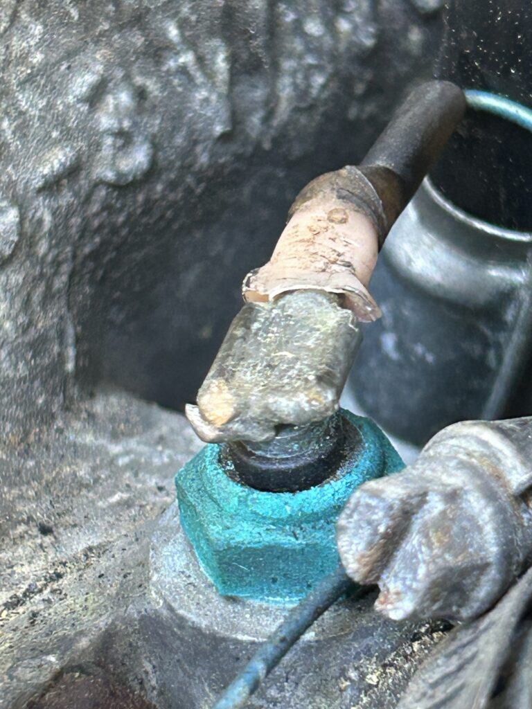
A cruddy looking temp sensor, but like the end is soldered on, so it must be fine right? No. No it was not. It turns out the core of the sensor was loose and when I would press on it with the multimeter to read the value, it made contact and was fine. Remove the probe and it would make no contact internally. Well, measuring this with the engine running, and pressing on it in just the right way, the Idle control circuit sprung to life! I jiggled the sensor, idle speed contol stopped. I pressed on the sensor, Idle speed control resumed….
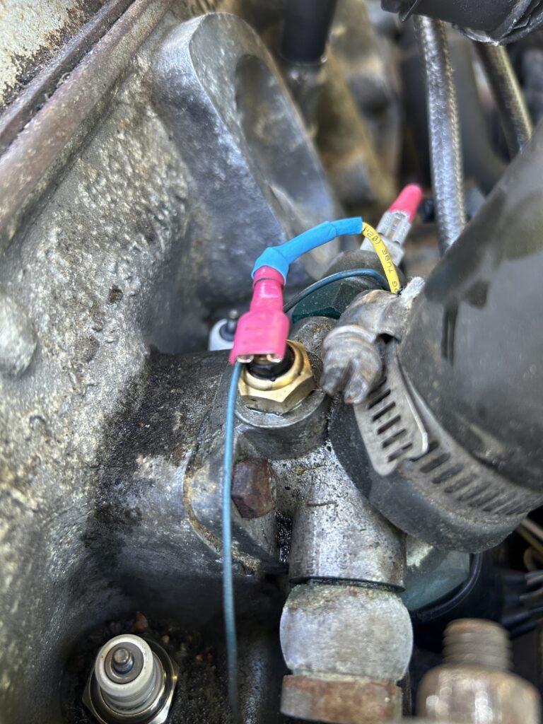
$8 later and little wiring work later things looked and worked a lot better!
Now, please dear reader, forgive me at this point for not checking the temp sensor more closely. The fact of the matter is, this car has more temperature switches and sensors than I’ve ever seen on a car, and it’s not always clear which one goes to which. After two years however, I now have a decent understanding of all the ways this car cares about temperature.
- A temp sensor for the ECU
- A temp sensor for the Idle Circuit
- A temp sensor for the gauge on the dash
- A temp sensor for the warning light on the dash.
- A dual stage temp switch in the radiator for the fan
- A temp switch in the thermostat housing for the after-run fan
- A temp switch under the fuel injectors for the injector cooling fan.
Anyway, at this point, I’ve verified they’re all working! AND I HAVE IDLE SPEED CONTROL. I had to readjust my idle baseline again, but that’s fine because, it idles when it’s cold. And the idle goes up when the AC compressor kicks on. And the idle stays high when coasting to stop (kinda, more on that later). And the idle kicks up when the 500W cooling fan kicks on. Amazing.
At this point, it still doesn’t run great when cold, and it started stalling at stop lights, and I’m still not getting ECU modulated boost, only mechanical waste gate level boost. I’ll cover these in Part 2!